Close


  • by
    Article Preview

    So I found some SVO switches on Craigslist with a hacked up harness for a decent price so I can re-purpose them in my Capri. I have 4 total - One works as it should, one does nothing and the other 2 power my stuff but the lights don't work...so I had to tinker...

    I know it's "just a switch" but it's awesome to see how this particular one works...lol

    The base of the switch is made of 2 halves held together with clips and covered with a trim plate...
    ...
    Read More Read More
    by Published on 09-13-2013 06:15 AM
    Article Preview

    A BEGINNER STEP BY STEP HOW-TO: FLARE A BRAKE LINE

    End preparation is quite critical to ensure the integrity ...
    Read More Read More
    by  Number of Views: 15922 
    Article Preview

    This will help those of you who have gone to service your rear (change axles, replace seals/bearings, change gears, etc.) ...
    Read More Read More
    3 Comments
    Published on 06-26-2013 03:45 PM

    Written by JACook

    01-06-2011

    Necessity being the mother of invention, I recently set about to find a way to repair the fuel gauge sender on my '85 CFI Vert.

    The '83-'86 CFI and EFI fuel gauge senders, Ford part number E3ZZ-9375-C, are no longer available from Ford, and none of the usual sources are able to find NOS ones anymore. What's worse, they are not reproduced by anyone in the aftermarket, even though they seem to have a higher failure rate than the senders for the carbureted cars, which are reproduced. I don't know if it's because the people selling the senders are unaware of the unique nature of these senders, but whatever the reason, I really like having a gas gauge that works.

    The '83-'86 CFI/EFI sender is very different from the sender for the carbureted cars. It's actually a lot like the sender for the '87-'93 cars, but the resistance range is 80 Ohms empty and 10 Ohms full, while the '87-'93 sender is 10 Ohms empty and 165 Ohms hen the tank is full. Since I wasn't having any luck finding the E3ZZ sender, I started looking around for other Ford senders that could be used as organ donors, to repair my existing sender.

    The CFI/EFI style senders use a ceramic printed circuit resistance strip, unlike the wire-wound resistor elements in the carbureted cars. Over time, wear and corrosion from oxygenated fuels take their toll, and the result looks like this-

    Worn out original resistance strip

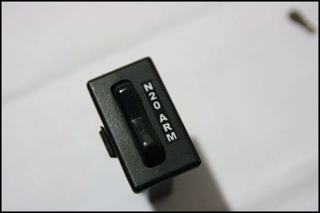
    For this particular sender repair, I ended up finding a donor from a very unexpected source. Dorman Factory Solutions makes a line of factory replacement fuel gauge senders, and the one I used is for, of all things, the 1984-1987 Tempo/Topaz, 2.3 Liter, without fuel injection. Who knew? This sender is Dorman part number 692-120, or Ford part number E63Z-9275-A.

    Here is the donor sender, alongside the original unit from my '85 (the grungy looking one).

    Original E3ZZ-9275-C sender alongside the donor sender.

    The senders are very different, but that doesn't matter, because we're only going to use one part. Well, maybe two, if your original float is not serviceable. It may be possible to use more of the parts from the donor sender, but there are differences that would make that a bit more work. More about that in just a bit.

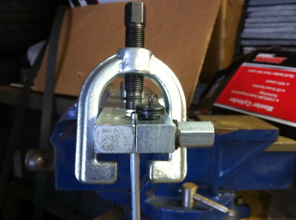
    First thing we need to do is take the senders apart. The float arm is a press fit into the old sender, and will need to be pulled out before removing the sender cover. I used a pair of needle-nose pliers to gently lever the arm out of the wiper. On the new sender, the float arm is a bit easier to remove. Once the float arms are off, the housing unclips from the metal backing plate, leaving you with something that looks like this-

    Original sender housing and wiper removed

    (Yours will still have a wire soldered to the resistance strip.)

    The new sender had some of it's pins heat-smashed on the back side of the plate, but once I trimmed those, I was able to unclip the housing just ...

    Read More Read More
    3 Comments
    Published on 06-26-2013 03:43 PM

    Provided by varn82

    Tools Required:

    - 3/8 Ratchet
    - 1/2" Socket
    - T45 Socket
    - 5/16 Socket
    - 2mm Allen Key
    - Razor Blades
    - Side Cutters
    - Hog Rings
    - Pliers
    - Phillips & Fllathead Screwdrivers
    - Staple Gun

    Current condition of drivers seat. Not bad for 20 years old.

    seats_01.jpg

    First step after seat removal is to separate the seat upper and lower frames. This is accomplished by removing the 2 Phillips head screws from outboard trim cover of seat back adjustment mechanism. Then remove (1) T45 Torx bolt from inboard side, and (2) 1/2 inch bolts from outboard side. (note, if vehicle is equipped with upper power lumbar adjustment, removed plastic vacuum line from lower seat section.)

    seats_02.jpg seats_03.jpg

    Part 1 - Lower Seat Cover

    We will start with recovering the lower seat frame. First step is to remove the 2 small roll pins from the adjustable knee bolster support (if equipped). This section will slide out after pins are removed.

    seats_04.jpg

    If seat is equipped with adjustable side bolsters, remove knob by loosening the 2mm allen set screw. The knob will slide off afterwards.

    seats_06.jpg


    Switch for power lumbar support is removed by lifting up on trim plate, and removing (2) Phillips head screws on switch. wiring and vacuum lines will come out with switch.

    seats_07.jpg seats_08.jpg


    Start removal of seat cover by first removing 4 plastic retainers on frame by rolling upward on them, secondly snip hog rings securing seat cover piping to frame.

    seats_05.jpg seats_09.jpg


    Fold seat cover sides up, and cut 2 hog rings on each side where metal seat cushion rods are secured to side bolster adjustment flaps. Also cut hog rings along front of seat frame. Now fold seat cushion/cover upward from rear, and slide off of rods. rods will stay attached to seat frame.

    seats_10.jpg


    Here is lower seat frame ready for assembly. I opted to remove the power lumbar, so i removed the hoses, wires and motor assembly.

    seats_11.jpg

    Place seat cushion on lower seat frame. Slide seat cover over metal securing rods.

    seats_12.jpg


    Remove metal rods from old seat cover and install in new seat cover.

    seats_13.jpg

    Start re-ringing seat cover to cushion and frame. Install rings where originals were removed from.

    seats_14.jpg

    Pull seat cover down and over to attach the plastic recurring strips to the frame. Also be sure to re-ring the seat cover piping to frame, for proper stretch on cover.

    seats_15.jpg seats_16.jpg


    Part 2 - Lower Knee Bolster


    Start by removing (4) 5/16 bolts from frame to cushion support.

    seats_17.jpg


    Place knee bolster cushion and support inside new cover, and staple with 1/4 inch staples, pulling tight over cushion. Bolt frame back to new bolster. Reinstall in seat frame and reinstall roll pins in brackets.

    seats_18.jpg seats_19.jpg


    Here is the finished lower seat frame/knee bolster assembly.

    seats_20.jpg


    Part 3- Upper Seat Cover and Final Assembly


    Factory seat cover is secured at bottom with a zipper. Unzip seat cover, reach up back of seat cover and push in on retaining tab for headrest, now remove headrest.

    seats_21.jpg


    Removed headrest guide by pulling upward on it, it takes some effort, but pulls out of top. Also remove trim bezel for rear seat entry level by removing (1) Phillips screw.

    seats_23.jpg


    Fold front of seat cover up slightly to access ...

    Read More Read More
    Published on 06-26-2013 03:41 PM

    Over the years I've made up lots of plug wire sets for myself and friends of mine. It can help give your motor that extra little attention to detail that can set it apart from everyone else, and give it a nice clean look.

    In this article I'll show you step-by-step how to do this. It's pretty simple, and just takes a little time and patience. Of course, you'll need to go out and buy another special tool for this job. Here's what you'll need to pull this off:
    • A pair of medium-size wire cutters
    • A pair of pliers
    • A special spark plug terminal crimping tool

    My crimping tool is from MSD - Part Number 3505. This is available from lots of places on the internet; just type the PN into www.froogle.com and pick your merchant.  This is a great professional-quality crimper. You can also buy all kinds of jaw inserts for many other types of crimping applications. The tool is shown below.


    I used some FRPP wires because they were the right color, and the right price. I removed all the lettering on them with brake cleaner and a towel. These are great wires, but they come a bit long and I wasn't satisfied with the fitment. Since these wires already had ends on them, I had to cut them off and install some new ones I picked up from a local performance shop.

    Lots of plug wires are available from manufacturers like MSD, Taylor, Moroso, LiveWires, etc. Many of these companies offer kits without the terminals installed so you can cut and crimp them to fit your motor perfectly. That's what we're going to do in this article.

    So down to business... You need to mock up all your spark plug wires in their respective locations. Starting at the post marked #1 on the distributor cap and moving counter-clockwise, the order is 1-3-7-2-6-5-4-8. You can mark the cap with a sharpie or scratch the numbers in with an awl if it helps you.

    Here are my passenger side wires loose.


    ...and the driver side wires just after I started looming them with zip ties.


    Since I don't have tons of money for fancy billet plug wire separators, I just use zip ties. It may not be as fancy but it comes out looking pretty clean and it's a lot cheaper! Simply wrap a medium size zip tie around the plug wires, and then a smaller one goes around the medium one between each plug wire.

    Starting from the spark plugs, carefully loom up the plug wires moving toward the distributor so they fit exactly how you like them. You'll have a bunch of wire hanging over at the distributor cap, but that's okay - we'll fix that later.

    Here's what mine looked like when I was done looming up the passenger side.


    Now you need to starting cutting the plug wires to length and installing the new terminals. As I mentioned earlier, I used FRPP wires which already have ends installed. You can simply pull the rubber boot off the end that attaches to the distributor and it will look like this.


    If you want, go ahead and snap it onto the distributor so you can see how they fit.


    Here are the new terminals I picked up. I think these are from MSD. These are the correct ones for the distributor end of your 5.0 Ford. If you're making wires for a different kind of car, make sure that you get the correct terminals for your application.
    Read More Read More
    1 Comment
    Published on 06-26-2013 03:36 PM
    Categories:
    1. Body

    Restoring Marchal Lights

    -Supplies Needed-

    • Lights, of course
    • Masking Tape
    • X-acto Blade or sharp razor blade
    • SEM High Build Primer
    • SEM Trim Black Paint
    • 220/320/400 Grit Sand Paper
    • Glass Bead Blaster Cabinet (optional, but very helpful)


    This light that is in need of some restoration.

    This is a single light I was just recently working on. I will also be using pictures of a pair of lights that I just restored. So, you may see some pictures that have a pitted lens and others that have a nice clear lens.


    At this time I do not have a remedy for fixing the pitted glass, but, I am working on it.
    I was hoping to use this glass to experiment with, but I shattered it in the glass bead blaster trying to clean the trim ring.
    NOTE: Do NOT bead blast the trim ring while the glass is still in place. This is the second time I have shattered one and I really thought I had it protected enough this time with masking tape. NOPE!


    First, we start by unscrewing the 2 screws on the front of the light with a flat blade screwdriver


    Gently pry open the casing, the black seal around the light can hold it on pretty well, so you have to use some force but don’t pull to hard as the light bulb holder is still attached to the wires inside and is fragile. The "Made in France" Marchal’s have a white ceramic holder while this "Made In Belgium" one seems to have a holder made of a different material. The Belgian ones are a bit stronger from what I have seen.


    Disconnect the 2 wires to the bulb holder


    Release the bulb holder by unlocking the metal hold down and remove it from the reflector.


    Now you can take out the light bulb/holder and set it aside
    NOTE: Don’t touch the bulb with your fingers, as the oils will harm the bulb and cause it to burn out prematurely.


    Unscrew the 2 screws from the retaining nuts near the reflector from the cover screws. The French ones have metal nuts, the Belgian ones have plastic screw-on washers.


    Now you can remove the reflector and set it aside.
    NOTE: Set it aside face down to keep dust and particles off the reflector. The less you have to touch that surface the better, as it scratches very easily. If you get some dust on it, I would use compressed air to remove particles before using a cleaner on it. Also, if your reflector is shot and peeling, I am going to be experimenting with some other stuff so you can try to reuse them. Some thoughts of mine are the chrome-type tape that is used in the HVAC field for heating ducts, etc. I will report back on that more later.
    Here you can see where it says Made In Belgium.


    Now you will want to slide the wires out from under the metal brackets, then use some needle nose pliers to squeeze the grommet so it will slide the wires out of the rear housing. Just pinch the grommet and gently pull the wires out the back.


    So, you should now have a pile of parts ready to work on.


    The Belgian lights have a painted-on cat on the inside, the French ones have a metal cat on the outside. 9 times out of 10 the metal cat has fallen off and never to be seen again. So I am painting it back on these which were painted anyway.


    At this point if you DO NOT have any rust issues* on the trim ring and will not need to bead blast it, you will not have to remove the glass. I will update this when I remove the glass from my next set. I used a brush and warm water to cleaned all the dirt out. It was enough to remove the cat on the inside. I am sure that some lacquer thinner would wipe the cat off if needed.


    Once clean, dry them out with some compressed air, then get it ready for masking.

    *If you have some rust issues, you will need to cut the gasket out from the glass and remove the lens. (No pics yet)
    Here are the rust issues I have with this one.


    *Ok, if you don’t have rust issues, then mask it up.


    You can now sand down the trim ring with some 320/400 paper and prime it up.
    I have been using SEM High Build Primer in black.


    After the primer has dried, sand it out smooth with some 400 paper. The high build works great as it hides most imperfections, especially if you’re not a good body man

    *If you have rust issues, then after the glass is removed (yes mine was still in here but I broke it this way remember) you will need to bead blast it clean.
    If you have body filler, this is the time to get that on there for the rough spots. If not, well, you can prime and paint over these areas now that the rust is gone but it won’t be as pretty.


    Once the filler has cured you can shape it down smooth with some heavier 220 grit paper then finishing it with the 320 and 400


    You can now paint your trim rings after they have been primed and sanded smooth as described above.

    I used SEM Trim Black.


    This is the single trim ring that had all the rust.


    At this point I was lucky to have a metal cat still around so I used it as a template.
    I laid it down in the cut out and traced over the tape with an X-acto razor blade.


    I used some High Temp Black paint, I had some VHT Black Brake Caliper Paint laying around so that worked for me.
    Spray the cat black on the exposed glass area.
    Then Peel off the masking tape after it has dried.

    Read More Read More
    1 Comment
    Published on 06-26-2013 03:33 PM
    Categories:
    1. Body

    Ford manual for fixing those infamous T-top leaks on Fox Mustangs and Capris. Thanks to member TL86LX for sending these images to FEP for use on this website.
    Click here to see the complete repair ...
    Read More Read More
    1 Comment
    Published on 06-26-2013 03:27 PM
    Categories:
    1. Body

    Scans showing the various bits and parts of Capris from 1979-1986. Submitted by FEP member caprisvo. List includes both body and mechanical parts.
    Click here to see the parts list.
    ...
    Read More Read More
    2 Comments
    Published on 06-26-2013 03:18 PM

    How to move the battery to the rear of your 79-86 Mustang or Capri safely, and within NHRA specifications.

    Article by Mike Croke.

    Due to the fact that most of those who are performing a battery relocation are likely to be drag racers, the following article shows how to do an NHRA legal install. Road racing sanctioning bodies are likely to have slightly different requirements, so consult the rule book of your particular sanctioning body to be sure of your legality.

    From the NHRA rulebook:

    "8.1 BATTERIES

    All batteries must be securely mounted and may not be relocated into the driver or passenger compartments. Rear firewall of .024-inch (.6 mm) steel or .032-inch (.8 mm) aluminum (including package tray) required when battery is re-located in trunk. In lieu of rear firewall, battery may be located in a sealed .024-inch (.6 mm) or .032-inch (.8 mm) aluminum, or FIA accepted poly box. If sealed box is used in lieu of rear firewall, box may not be used to secure battery, and must be vented outside of body. Strapping tape prohibited. A maximum of two automobile batteries, or 150 pounds (68 kg) combined maximum weight (unless otherwise specified in Class Requirements) is permitted. Metal battery hold-down straps mandatory. Hold-down bolts must be minimum 3/8-inch (9.53 mm) if battery is relocated from stock and other than stock hold-downs are used ("J" hooks prohibited or must have open end welded shut.).

    ...

    8.4 MASTER CUTOFF

    Mandatory when battery is relocated, or as outlined in Class Requirements. An electrical power cutoff switch (one only) must be installed on the rearmost part of each vehicle and be easily accessible from outside the car body. This cutoff switch must be connected to the positive side of the electrical system and must stop all ...

    Read More Read More